The core balsa wood stick frame- work of an ML-307 consisted of five (5) sticks, 4 about 25 inches long (blue and green sticks) and the fifth about 50 inches (forming the main axis -- red stick). Together they formed 3 right- angle axes, each about 50" long. A special metal hinge at the center connected all core sticks together, and was designed to enable the complete target to fold down flat for easier transport and storage. The shorter blue and green sticks rotated around the long red main axis stick, as will be shown later.
2 sets of sticks (here represented by the red and green sticks) were rectangular in cross-section (measuring about 10mm x 6mm). The other set (blue here) were smaller and square (about 6mm x 6mm).
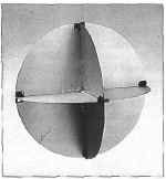
The frame was tilted like a child's metal jack and rested on a triangular base. ( 3-D drawings generated by the POVwin ray tracing program.)
Complete Frame
Six (6) diagonal balsa sticks were connected across the ends of the core sticks. Each of these sticks was about 35" (2'11") long. Thicknesses were the same as for the core sticks (4 thicker rectangular sticks -- violet and orange here -- and 2 thinner square sticks -- light blue).
The total length of the 6 core 25" sticks and 6 diagonal 35" sticks was about 30 feet.
The complete framework formed four reflecting triangular corners, one with the base facing straight down, and 3 outward facing corners.
KEY POINT: The light blue diagonal sticks were removable so that the target could be folded down flat. Since the targets came 24 to a pack, this meant there were up to four dozen loose sticks per pack, sources of potential extra sticks in the Fort Worth photos.
Basic Principle of a Radar Target Corner Reflector
If you make a square corner out of mirrors, a light shown at the corner from any angle will always bounce directly back towards the source. Although only a 2-dimensional corner is shown here, the same is also true for a 3-dimensional corner, such as the corner of a room.
Radar waves are just another form of light, and will likewise bounce directly back towards the radar source if reflected from a square corner. Thus corners create very strong radar returns. For this reason, small boats frequently have corner reflectors hung from their masts to make them more detectable to the radar of large ships. In contrast, radar stealthy planes and ships endeavor to round off all surfaces and get rid of the strong-reflecting corners.
Corner reflectors are also sometimes referred to as trihedral (because of 3 intersecting surfaces) or corner cube reflectors.
Weather RADar WINd Targets or RAWINs
Radar targets were first developed during WWII by the Army Signal Corp to enable tracking of weather balloons by radar and precision calculation of wind speed and direction at various altitudes. After the war, the military distributed surplus targets to the civilian weather bureau, who used them on occasion, in addition to the Army meteorological services, artillery units, and some special projects, like Project Mogul in New Mexico.
RAWINs are basically a balsa-wood kite stick framework forming corners covered with a radar reflecting substance like aluminum foil.
The Mogul Project occasionally used the ML-307 radar target for tracking of their balloon trains. This is also the model of RAWIN displayed in Gen. Ramey's office on July 8, 1947. The contention of Roswell skeptics is that what Ramey displayed necessarily came from a Mogul crash and represented the remains of multiple radar reflectors. Before we can properly analyze this claim, it is necessary to know the basics of how the ML-307 was constructed.
Foil/Paper Panels
Each outward facing corner consisted of 3 right triangles measuring about 25" x 25" x 35". Sheets of a laminated foil/paper material (similar to that used to wrap chewing gum or candy bars) were connected to the balsa framework with common white wood glue and plastic acetate tape similar to or identical with household Scotch tape.
The paper backing for the foil was usually white. Note that it lines the whole upper surface of the target .
The foil surface lined the 2 upper triangles of each outward-facing corners. It is depicted here as light blue. Usually the bottom triangle of each outer corner was the paper surface, while the bottom facing corner, sharing these bottom triangles, was lined with foil.
Complete Target with Sheaths
The 6 outer diagonal sticks had the foil/paper wrapped around them, forming sheaths with the sticks inside them. The bottom triangular panels without sticks also had the foil/paper folded back for reinforcement of the edges.
Three of these fold-back strips had the foil side facing out, forming foil strips on the edges of the white paper (light blue strips pointed to by blue arrows). The two on top were the sheaths for the removable diagonal sticks. There was another foil strip for the bottom panel of the right corner (other blue arrow). All 3 foil strips folded inward into the corner for target fold-down.
The other strips had the paper-side facing out forming white strips on foil (2 indicated by white arrows). These remained straight and did not fold-down.
Larger Foil-Paper Panels
To simplify construction, the 9 smaller corner triangles were made up from one larger square panel (forming 4 smaller triangles), 2 large triangles, and one small triangle.
This is depicted at the right, with the various panels color-coded to correspond with construction detailed below. Note that all the panels could be economically constructed from square sheets 3 feet or 36" on a side (also providing the extra material for the fold-back edge strips.)
At the bottom, the panels are depicted foil side up (as in the Fort Worth photos) with the white marker strips shown (foil strips would be underneath and not visible). The various color- coded core and diagonal sticks are laid out on the panels in their expected positions
What to look for
A proper accounting of debris in the Fort Worth photos requires locating these various components of an ML-307 target. In particular, one should be looking for extra foil-paper panels indicating debris from more than one target. However, there do not seem to be any. Instead all panels seem to be accounted for by one target. One should also search out the expected core and diagonal sticks, again looking for possible extras. There are probably 2 or 3 extra diagonals, but all of these appear to be of the removable variety that were to be added back into their sheaths after the target was unfolded for use. These extra sticks are all clean, lacking glue "bead" marks and still-attached foil-paper debris seen on the other sticks in the photos. A likely scenario would involve somebody not familiar with the targets grabbing one folded target out of shipping carton and a handful of loose sticks, not knowing that only 2 were needed to complete the target.)
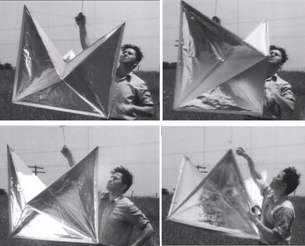
Various views of an ML-307 target. Shots taken from a 1947 AAF documentry of Ohio weather research project. Youtube video. (Also used by modern USAF to debunk Roswell.) Note this model lacks the paper fins at the top, added in 1951. Also note the white strip along some of the edges. This is NOT white tape with "flower patterns" on it, the so-called Mogul "flower tape." It is the white paper backing folded over to form a sheath for the edge sticks and also for edge reinforcement along the bottom triangle edges which lacked sticks.
A sailboat radar corner reflector consisting of 8 corners.
Since the Fort Worth photos depict the panels with the foil side up, the white, outward facing strips on the foil surface become excellent identification markers of the various foil-paper panels and any still-attached sticks. Four of these white strips are clearly visible in the photos.
To finish off the target, suspension twine was tied to the three top points and attached at the center to the main line. Later versions dating from 1951 onward also had glued and taped-on paper "fins" at the top with additional twine. They have been omitted since they wouldn't be relevant to what was shown in 1947.
(although all would either be inside a sheath or on the other side of the panel under the foil glued to the paper side).
Understanding the number and shapes of the panels plus the relative layout of the sticks within the panels is important in reconstructing the radar target in the Fort Worth photos and determining exactly how much debris is there. Is it one radar target or more than one?
Assembly of the Panels
The next three diagrams illustrate how the color-coded foil/paper panels would have been attached to the complete balsa stick framework. First the large, yellow square panel (diagram at left) would be folded along a diagonal and then glued on the paper side to the main core axis stick (red). This would then form the bottom triangles of the left and rear corners and the "roof" or 2 upper triangles of the right corner.
(A notch has been cut in the left front corner triangle to help see the bottom triangle behind it for the rear corner.)
The large, pink triangular panel formed the roof of the rear corner (center diagram).
Finishing off the target, the large blue triangular panel formed the roof of the left corner, while the small green triangle formed the floor of the right, front corner (right diagram).
Folding and Unfolding the Target
The ML-307 RAWINs were designed to be folded flat for more economical storage and transport. Unfolding them for use was obviously just the reverse.
The triangular panels with the foil edge strips folded into the three corners during the fold-down process. These marker fold-in foil sheaths are shown from two vantage points below and pointed to by the blue arrows. (The white edge strips have been removed to better show the other diagonal sticks.)
Two of these foil strips on the upper surfaces were actually sheaths for diagonal framework sticks. These sticks had to be removeable so that the target could fold down. They were actually inserted into the sheaths (white arrows) and probably glued only after the target was finally unfolded for use.
Since the targets were packed 24 to a box, there were numerous unglued, unsecured sticks in the shipping and storage containers, free of any attached foil-paper. (Assembly instructions from one manufacturer, Alox kites of St. Louis, indicates 52 such loose sticks were packed per carton, providing 4 spare sticks for the 2 dozen targets). A few of these completely clean sticks may very well show up in the Fort Worth photos, suggesting they came not from a crash in the field but out of a box.
Unfolding of a target is shown in the animation below. Note how the 3 triangles with the foil strips are folded into the corners, and how all the various framework sticks rotate around the central red core stick as the target unfolds. Also notice that when folded down, the target was in the shape of one of the large triangles. (Stick thickness has been exaggerated for clarity.)
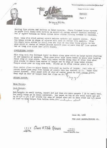
The document at right describes how the targets were packed, with 24 to a carton and 52 loose sticks thrown in at the top for final assembly of the targets by insertion of the last two edge sticks after the targets were unfolded. (These are instructions from one of the radar target manufacturers, Alox company of St. Louis, on how to assemble the targets and pack them for shipment.)
The relevant portion on packing states: "Put 6 targets in small carton, insert pad and then six more targets (12 to small box). Two small boxes go in large container. Lay paper on top of two small boxes and put in 52 1/4 x 1/4 x 36" sticks for edge of target, also put in data sheet, and 1/3 pound of cord to hang targets from balloon..."
Thus there were 48 loose sticks (plus 4 extras for possible breakage) thrown in on top of the radar targets to complete the 24 packed targets.
The rather complicated image at right is one of the 1947 Fort Worth photos of the radar target showing the torn foil-paper panels with various framework sticks identified. (To see full size, download or view in different window on your browser.) The letters identifying sticks and fragments are color-coded as above (red, green, blue core sticks; lavender, aqua, yellow diagonal sticks). Lettering is arbitrary. Letters A-H were labels for sticks used in an original analysis from 1994 by a government lab employed by the Air Force. They did only a partial analysis and came up with only about half of the total sticks. I have extended the analysis (and added more identifying letters) to try to include all sticks partially visible under the debris, outlined by foil, stick ends poking out of sheaths, and small broken fragments. Note some sticks are broken and composed of more than one fragment (e.g. B/B2/B3, C/C2, N1 & N2) Various hires photos of the debris were analyzed taken from different angles to try to visualize all the stick pieces, as noted in image legend. Some pieces not clearly visible in this photo can be seen in others.
The animation at right shows a 3D ray-traced reconstruction of the scene overlaid on the original image. 3D ray-tracing allows the dimensions of the various sticks and other components to be accurately measured. In addition to the sticks, note that the approximate dimensions of the darkened balloon mass were determined and the volume of the balloon debris calculated. This turns out to be about the volume of a shoe box, thus hardly any balloon debris, likely accounted for by one balloon. One balloon and one radar target was also the official story of Gen. Roger Ramey (kneeling) back in 1947.
This graphic shows the same graphic as above of foil-paper panels used in construction with how the framework sticks were laid out in relation to them. This time, however, the various lettered sticks and fragments from the photos are laid out in a proposed reconstruction of what was in the photos.The torn foil-paper pieces attached to various pieces are also roughly drawn in (gray being visible foil and light blue missing portions), showing that most can be accounted for and are again consistent with only one radar target in the photo. Portions of sticks in gray (C2, P, Q) are sticks for which there is ambiguity about visibility and length. (E.g., they might be outlined inside their foil-paper sheaths, or maybe this is a partial illusion of the stiffness of the foil-paper--we are seeing only a "ghost" or mold of the stick.)
Again, the key point is that the debris is consistent with one and only one radar target in the photos. However, there are also three extra aqua sticks (D, W, H), pictured outside the panels at the bottom of the graphic. These correspond to the thin, bare edge sticks that are left out of the radar targets so they can be folded down for packing and shipment. As I have noted above, they are packed separate from the targets themselves, with at least 48 thrown on top of 24 folded-down radar targets.
These extra sticks are most economically accounted for by one new target being removed from a packing box and assembled (then broken by hand), with several extra bare edge sticks being grabbed in the process and thrown in the mix.
A much harder to believe scenario would be more than one radar target recovered in the field and rolled into one bundle(rancher's story), which when unbundled seem to add up to only one radar target, no other panels with sticks inside of their sheaths, and a few bare sticks outside of panels with no fragments of foil glued to them (as would be true if they came from a previously-assembled target).
The same applies to the balloon debris. The rancher's story was of finding only small "rubber strips" and again rolling them into another bundle. How believable is it when unbundled the multiple small rubber pieces would magically reassemble into the seemingly intact weather balloon in the photos?
Another subtle detail in the photos is views of the white paper backing of the foil in the various photos shows only an even white color with no evidence of expected water staining from exposure to the elements for a supposed month. This also supports the idea that the radar target in the photos was a brand new one out of a box.